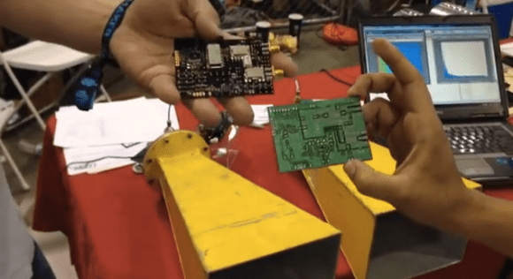
![greg_sar_radar]()
(photo taken by Matt Metts)
Sensors. The low-end stuff that we can get our hands on usually suffers from poor range, lack of sensitivity, and no way to characterize what the target is. But today we can use the good stuff that, until recently, was only available to military: radar. In this post we will discuss how radar works, commercially available small radar devices, and where to learn more to help make it easy to add radar to your next project. Reach out and sense something!
Radar Basics

Radar uses a radio transmitter and receiver to measure the time of flight from a transmitted radio wave that scatters off a target back to the receiver.
Radar is simple, it consists of a radio transmitter and receiver. Radar is a World War Two acronym meaning Radio Direction and Ranging, in other words a radar consists of a radio transmitter and receiver where the range to an object is measured by clocking the time between the transmitter transmitting a known modulated waveform and the receiver receiving this waveform scattered from a target.
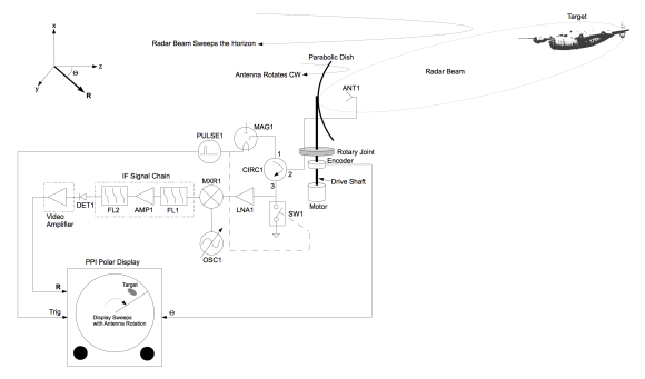
![basic_pulsed_radar]()
This block diagram represents a conventional radar that comes to mind when you think about radar, you might find this design used on a fishing boat or commercial aircraft.
One enabling technology for Radar was the cathode ray tube (CRT), which facilitated a method of measuring the time delay between transmitted and received waveforms. This led to the development of numerous radar sensors used in the second world war, which generally followed the Plan Position Indicator (PPI) architecture.
Toady, rather than using a CRT we can use high-speed digitizers. This offers the obvious advantage of applying signal processing to acquired data so that only moving targets are detected, tracking can be achieved, imaging, and a multitude of other modes.
But for hobbyist and consumer projects we do not need this much power, range, and can not afford the cost. We need the ability to sense like a long range radar (detecting only moving targets, imaging, Doppler, signatures, etc) but at short ranges and at low costs.
Very few off-shelf small radar options exist as of today. In this post we’ll review these, their basic architectures, and direct you on the next steps.
Continuous Wave (CW) Doppler Radar

How CW Doppler radar works.
If you are not interested in ranging or imaging but would like to measure velocities or radar signatures then consider CW Doppler radar. CW Doppler radar works by feeding the output of a CW oscillator to an antenna and radiates that carrier towards a moving target. This carrier scatters off the moving target back to the receive antenna where it is amplified and fed to a frequency mixer. The mixer mixes the oscillator and the scattered carrier resulting in a Doppler shift product. This product is the Doppler shift off of the carrier’s center frequency and is generally in the KHz range. Low enough to be easily digitized by the audio input port of a laptop computer or other low-cost digitizer.
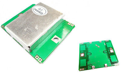
![Chinese CW doppler radar]()
A low-cost X-band CW Doppler Radar Module, readily available on Ebay.
Try a CW Doppler radar. You can hack an old police radar gun by locating the video amplifier or mixer’s output and plugging that signal into the audio input port of your laptop and displaying this data using a ‘water fall’ Fourier transform.
If you find an old motion sensor or door opener. These typically use CW Doppler radar modules known as Gunnplexers. Hack into one just as you would with the Police radar.
Or, you can procure new off-shelf X-band CW Doppler radar devices from China for < $10 on Ebay. I’ve used these devices before, they do work but have limited range. This may not matter for your project.
Impulse Radar
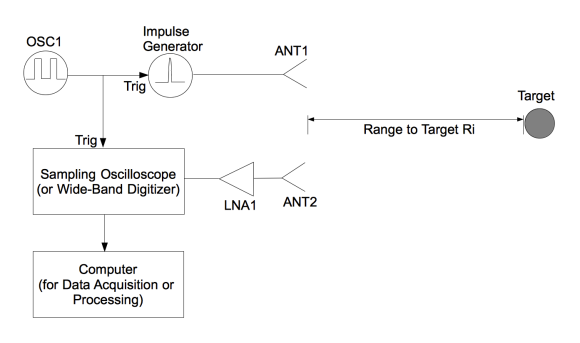
![basic_impulse_radar]()
The most basic impulse radar simply feeds the output of the impulse generator directly to the transmit antenna. Scattered impulses are amplified and digitized.
Short range radars sense at 150m or less. At these short ranges extremely short pulses (meaning short in time duration, nS or pS in duration) are required to provide sufficient resolution to be useful. Short pulse, or impulse radar systems, generally follow a simple architecture where the impulse generator is often tied directly to a transmit antenna and a low noise amplifier (LNA) is tied to a receive antenna. A high speed digitizer is triggered off the impulse generator and acquires data on the output of the LNA.

Novelda manufactures single-chip impulse radar devices.
You can incorporate impulse radar technology into your next project. Commercial versions of impulse radars are available to hobbyists and developers. Most notable are the ASIC based impulse radar manufactured by Novelda. These devices do require external antennas but contain on-board radar and high speed digitizers.
Additional impulse radar systems are being manufactured in quantity for automotive applications (blind spot detection, parking aids, etc), but details on these are not easy to find unless you directly engage the manufacturers. Manufacturers of automotive radar equipment include, Delphi, Continental, TRW, Bosch, Denso, and Autoliv.
Frequency Modulated Continuous Wave (FMCW) Radar
FMCW radar was originally used in radar altimeters starting in the 1930′s. Today, FMCW radar is the leading short-range radar architecture because it offers short-pulse radar resolution while providing significantly greater sensitivity with the same peak transmit power. This is because FMCW radars transmit continuously and leverage the discrete Fourier transform (DFT) to increase SNR in proportion to the time over which the DFT is applied. But for a hobbyist the key take-away is that these radars use a simple architecture and radar signals can be acquired by low-bandwidth digitizers such as the audio input port on your laptop, ADC input ports on micro controllers, the lower cost National Instruments NIDAQ units, etc.
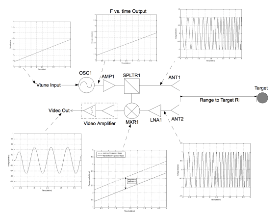
![coherent_FMCW_radar]()
How FMCW radar works.
For an FMCW radar, a CW oscillator is frequency modulated with a linear ramp. In other words, the CW oscillator starts at one frequency and ramps-up to a second over a relatively long period of time (0.5-10 uS). This waveform is radiated out of the transmit antenna towards the target scene. Some of this waveform is fed to the receiver mixer. What is scattered off the target is amplified by the LNA and fed into the receive mixer where it is mixed with the transmit waveform. The mixing product results in a low frequency (KHz range) beat tone that is proportional to range. The higher the frequency of beat tone the further the target. If measuring a multitude of targets then expect to see a multitude of beat tones superimposed on each other. To measure the range to targets you digitize with a low bandwidth digitizer being careful to synchronize the digitizer’s trigger with the start of the up-ramp. With this digitized data for each up-ramp, apply the DFT. This results in a time domain representation of the round trip time from transmitter, to targets, and back to receiver.
![KCL-1]()
![coffe can radar photo res-ll-003iap11]()
![QDM radar kit]()
![k650q-Arduino+Radar_teaser]()
Add an FMCW radar to your next project. FMCW radar devices are available for developers and hobbyists. Some of the lowest cost FMCW radar devices are manufactured by RF Beam Microwave GmbH, who offers 24 GHz FMCW radar modules for less than $10 in quantity, shown here is a K-LC1.
In addition to this, you can build your own ‘Coffee Can Radar’ from the MIT Opencourseware site.
Not interested in building your own coffee can radar from scratch? You can buy a ready-made coffee can radar kit form Quonset Microwave. This radar provides data via a USB or BlueTooth.
And coming soon will be the radar Arduino shield! Credit for this belongs to Tony Long, who developed this shield loosely based on the MIT Coffee Can radar.
Learn more
Add a radar sensor to your next project. It is not difficult to do with some basic understanding of architectures and signal processing. To learn more,
We can do this.
Soon small radar devices will be everywhere, let your project be one of the first!
![DSC_0318]() Gregory L. Charvat, is author of Small and Short-Range Radar systems, co-founder of Butterfly Network Inc., visiting research scientist at the Camera Culture Group MIT Media Lab, and editor of the Gregory L. Charvat Series on Practical Approaches to Electrical Engineering. He was a technical staff member at MIT Lincoln Laboratory from September 2007 to November 2011, where his work on through-wall radar won best paper at the 2010 MSS Tri-Services Radar Symposium and is an MIT Office of the Provost 2011 research highlight. He has taught short radar courses at the Massachusetts Institute of Technology, where his Build a Small Radar Sensor course was the top-ranked MIT professional education course in 2011 and has become widely adopted by other universities, laboratories, and private organizations. He has developed numerous rail SAR imaging sensors, phased array radar systems, and impulse radar systems; holds several patents; and has developed many other radar sensors and radio and audio equipment. He earned a Ph.D in electrical engineering in 2007, MSEE in 2003, and BSEE in 2002 from Michigan State University, and is a senior member of the IEEE, where he served on the steering committee for the 2010 and 2013 IEEE International Symposium on Phased Array Systems and Technology and chaired the IEEE Antennas and Propagation Society Boston Chapter from 2010-2011.
Gregory L. Charvat, is author of Small and Short-Range Radar systems, co-founder of Butterfly Network Inc., visiting research scientist at the Camera Culture Group MIT Media Lab, and editor of the Gregory L. Charvat Series on Practical Approaches to Electrical Engineering. He was a technical staff member at MIT Lincoln Laboratory from September 2007 to November 2011, where his work on through-wall radar won best paper at the 2010 MSS Tri-Services Radar Symposium and is an MIT Office of the Provost 2011 research highlight. He has taught short radar courses at the Massachusetts Institute of Technology, where his Build a Small Radar Sensor course was the top-ranked MIT professional education course in 2011 and has become widely adopted by other universities, laboratories, and private organizations. He has developed numerous rail SAR imaging sensors, phased array radar systems, and impulse radar systems; holds several patents; and has developed many other radar sensors and radio and audio equipment. He earned a Ph.D in electrical engineering in 2007, MSEE in 2003, and BSEE in 2002 from Michigan State University, and is a senior member of the IEEE, where he served on the steering committee for the 2010 and 2013 IEEE International Symposium on Phased Array Systems and Technology and chaired the IEEE Antennas and Propagation Society Boston Chapter from 2010-2011.
Filed under:
Featured,
news,
radio hacks ![]()
![]()


 The very first fully operational radar Arduino shield


 The project featured in this post is


